Visitor information
Overview
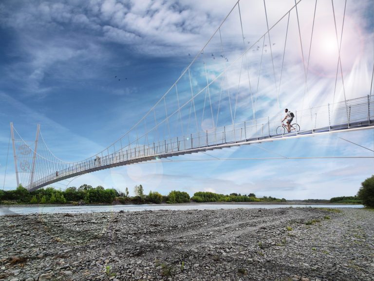
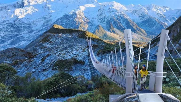
The Manganui Gorge Suspension Bridge is on the Manganui Gorge Track, Mount Taranaki. It’s a 100-metre-long footbridge. It’s built in a “swing bridge” style, but is very stable to walk on. The views from the bridge and the track are outstanding, with epic vistas of Mt Taranaki and east over the Taranaki plains.
DC Structures Studio won Gold at the 2024 ACE Awards for “exceptional consultancy services that set a new industry standard” on the Manganui Gorge Suspension Bridge project.
Accessing the Manganui Gorge Track
To get there, take Pembroke Road out of Stratford. Follow the road right to the end where you will find The Plateau carpark. The walking track to the bridge is signposted. The Manganui Gorge Track is a 30-minute walk from The Plateau carpark to Manganui Ski Area. The bridge is just 20 minutes’ walk from the carpark.
This bridge is part of the Around the Mountain Circuit.
Manganui Gorge Suspension Bridge visitor FAQ
Frequently asked questions.
How long is the walk to the bridge?
It’s a 20-minute walk from The Plateau carpark to the Manganui Gorge Suspension Bridge. It’s another 10-minute walk past the bridge to the Manganui Ski Area.
How difficult is the walk?
Easy-medium. There are some steep and uneven sections, and some steep drop-offs from the side of the track.
In fine weather this track should be suitable for most able-bodied people including supervised children and older people.
Note that Mt Taranaki can get icy and dangerous in cold weather. Also this is an alpine track where weather can change suddenly – be prepared!
Where should I park?
At The Plateau carpark, at the very end of Pembroke Road.
Will I cross the bridge walking around Mt Taranaki?
Yes, the Around the Mountain Circuit passes over the Manganui Gorge Suspension Bridge, as long as you take the upper track through the Manganui Gorge section (not the Curtis Falls Track).


Technical information
The Manganui Gorge Bridge is a 100m long suspension bridge close to the summit of Mt Taranaki located in New Plymouth, New Zealand. It has an impressive 93m clear span and is 1.2m wide and sits in close proximity to the existing ski-field. The purpose of the suspension bridge is to connect the “Around the Mountain” scenic walk and bypass the existing (potentially dangerous) access route through the base of the rocky gorge (which will be closed on completion of the suspension bridge).
Design of the suspension bridge was completed by DC Structures Studio for the Department of Conservation (DOC) in 2022 and is due for construction in 2023.
The overall Taranaki Crossing project will improve 25km of tracks, creating a mix of short walks and longer tramps. It will also minimise the impact of visitors on the maunga environment. It has ongoing support from Kānoa, the Regional Economic & Investment Unit, which has welcomed completion of the manganui Suspension Bridge (design). Operations manager Gareth Hopkins said “The new bridge will be a key feature of Taranaki Crossing, a network of upgraded track from Dawson Falls to Mangorei Rd end. The bridge designer [DC Structures Studio] has been working on an elegant yet strong design that sits slightly hidden up the Manganui Gorge”.


During the design process we have had strong collaborations with Ngāti Ruanui artists to help capture the story and mana (prestige & authority) representative of this iconic location and rich local culture. The mast and the balustrade panels will feature distinctive and unique mauri inspired artworks showcasing the various stages of the avalanche process. The suspension bridge features state-of-the-art long-life fiber reinforced polymer (FRP) decking in a custom colour of “Dulux Moeraki”. The decking colour was specifically selected by Ngāti Ruanui to coincide with the mountain’s existing colour palette.
")
A key part of our design process was to offer DOC the latest state-of-the art analysis techniques to help take their projects to the next level. We worked closely with the DOC Engineering Team to help showcase the latest thinking in the realms of aerodynamic assessment, pedestrian vibration, wind fatigue assessment, and cable failure assessment. We also demonstrated a clear and concise way to undertake value-added safety in design methods by focusing on details that would result in clear and tangible improvements to safety during both construction and maintenance (a key consideration for DOC). DOC were keen to see how these best-practice methods are considered, applied, and more importantly how they influence overall design and capital costs of projects.
“This project was far more that just designing a single bridge. It was more about helping DOC understand what the “next level” for rural suspension bridge design looks like both technically and also from a stakeholder collaboration perspective. It was about helping them set a best-practice benchmark for their future bridges.”
[Dan Crocker – Chief Bridge Architect & Engineer]
The suspension bridge has been designed to the latest national and international design standards including consideration of avalanche blast effects, aerodynamic instability effects, pedestrian vibration and associated user comfort, steel fatigue on steelwork and key components, and the bridge also considers the complex time history influence of cable failure scenarios (some of these aspects are discussed further below). The bridge is designed for “unlimited” live loading in accordance with the NZTA Bridge Manual v3.4 and thus is not subject to any maximum number of users (traditionally the case for DOC bridges) and thus risk of overloading is greatly reduced.
Overall, this bridge is intended to represent a new era in DOC suspension bridges with a core focus on “best practice” design and cultural collaboration.
Suspension bridge structure & configuration
The bridge is supported by two 16m and 25m high inclined steel masts at the northern and southern ends of the Manganui Gorge respectively. The zinc sprayed circular hollow section (CHS) steel masts will be tilted 9 degrees toward the gorge and form a distinctive silhouette. The masts are supported on reinforced concrete pads cast directly onto exposed rock at the existing walking tracks.

The superstructure is suspended from the masts using high strength Fatzer™ spiral strand cables. The cables are connected to the masts with proprietary cable forks and are coated with 5% aluminium + 95% zinc (AKA Galfan or Bezinel) to optimize durability.
The superstructure consists of two parallel flange channel (PFC) stringers spanning onto equal angle (EA) cross beams positioned at 1500mm horizontal increments along the span. The cross beams will be supported by EA hangers spaced at 3m centres along the bridge span and affixed to the cables with cable clamps. Use of these rigid EA hangers was a requirement of DOC and is aimed at improving rigidity of the deck (instead of cable hangers) in response to Ngati Ruanui’s original request for a “robust and stable structure”.
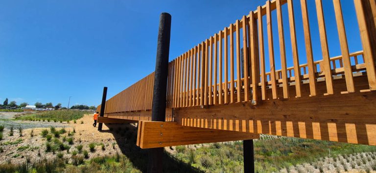
A 1.2m high EA balustrade post will be used at 3m centres alternating with the hangers. Spanning between the PFC stringers will be a 50mm thick proprietary Treadwell™ fibre reinforced polymer (FRP) decking mini-mesh system with integrated anti-slip coatings. This flooring has been
Parabolic wind cables connected to cross beams via transverse wind-stays restrain the superstructure in the lateral direction. They also have a vertical component to help stiffen the overall superstructure and add equivalent mass. The superstructure features equal angle plan bracing arranged in a Pratt truss configuration to span between the wind stay fixing points. The plan bracing also enables load to be directed to the south bankseat for the mast and superstructure regions not otherwise supported by wind-stays.
The balustrade is formed from a galvanized tubular handrail running between hangers and balustrade posts attached with a D-bolt clamp. The handrail will be positioned 1.2m above deck level. Small diameter stainless steel wire rope will run horizontally between hangers spaced at 90mm increments vertically.
Design life of bridge and coatings
In April 2022 we undertook a special study to consider the consequences of increasing the design life of the suspension bridge from 50 years (conventional for DOC bridges) to 100 years. We summarised that the net effect was negligible and the recommendation was made to consider the bridge as a 100 year structure (consistent with standard Waka Kotahi operating practices). This was agreed by DOC in May 2022.
Structural analysis modelling
Structural analysis modelling of the suspension bridge was performed using a 3D analysis model created in SAP2000 v24. Steel and concrete elements have been modelled as “frame” elements and stay-cables have been modelled as pre-tensioned “cable” elements with catenary action. See image below.

Where possible the modelling was run as non-linear load-cases. The only exception to this rule was the “modal” case as used for seismic, wind dynamics and pedestrian dynamics. The “modal” loadcase is run based on the stiffness at the end of the non-linear full permanent load case. This enables the modal case to consider the deflection behaviour and load take-up expected in the structure of the bridge when assessing dynamic performance.
Once the final condition was set, the structure was de-constructed in reverse order so that the staged stressing forces and anticipated deflection for construction could be determined. Since there are no creep/shrinkage related components (mast, super, cables are all steel) this reverse method was assumed adequate for design purposes.
Aerodynamic assessment of suspension bridge
Wind effects on the bridge have been considered in accordance with BD49/01 Design Rules for Aerodynamic effects on Bridges as referenced by the NZTABM v3.3. BD49/01 is an empirical code for assessing dynamic perfromance and is often found to be inapproapriate for narrow footbridges. Work was also supplemented by complex computational fluid dynamics (CFD) modelling of the suspension bridge (AKA a computer based wind tunnel).
The following is a summary of the BD49/01 empirical process applied to the Manganui Gorge Bridge:
The assessment to BD49/01 determined that further study is required to:
Aerodynamic CFD modelling of bridge
To close-out the further work highlighted by the BD49/01 checks, an independent Wind Study was performed. The work was performed by our specialist aerodynamic sub-consultant. See extracts from the CFD modelling below.


A key outcome of the CFD study was to quantify and validate the vortex excitation (a key measure of both comfort and fatigue in BD49/01). The CFD results are used on this basis to verify the BD49/01 assessment as required by BD49/01 clause 2.2. Amplitudes at various wind incidents were recorded for the ULS 58m/s wind speed. As shown confirmed by CFD sensitivity checking these amplitudes can be factored by the square of the velocity to obtain amplitudes at other wind velocities. The CFD also confirmed that the natural frequency for wind vortices occurs in the range of 2 to 3m/s wind events which is consistent with the BD49/01 predictions (≈2m/s). If we focus on the worsecase 58m/s porous deck oscillation of 26mm at -2.5 degree pitch and factor by (2.5m/s)2 / (58m/s)2 = 0.0019 we produce a vertical oscillation estimate of 5mm. This compares well with the BD49/01 estimate of 2mm.
Using the 5mm CFD developed oscillation would produce a “Dynamic Sensitivity Factor” (kD) value of 8mm/s2 (rather than 2mm/s2). According to Table 1 of BD49/01 this level of excitation is at the extents of the “tolerable” range (<8mm/s2) and vertical load is considered below 4% of the dead loading and does not require fatigue assessment.
From the amplitude data it can be observed that the porous deck produces vertical amplitudes 6% of those from a solid deck which is a major advantage with regard to comfort and fatigue. We noted that if a non-porous deck were used the consistency with BD49/01 would not so easily be justified and the deck would likely move in to the “unpleasant” range and be subject to further fatigue assessment. This is something that should be born in mind by DOC and others on future projects not utilizing porous decks or not having CFD analysis (both used here on Manganui Gorge Bridge).
The CFD model was also used to confirm that torsional divergence, when considered for the more complex formula of Eurocode EN 1991-1-4(2010) Annex E.4.3, was found to occur at wind speeds well in excess of 50m/s and thus were not considered an issue.
Pedestrian vibration of suspension bridge
Pedestrian vibration was considered in accordance with Design of Lightweight Footbridges for Human Induced Vibrations (JRC-ECCS, 2009). This is an international and well-respected code in the field of pedestrian vibration.
As per the ECCS Guide Section 4.2 vertical effects are only considered in the natural frequency range of 1.25Hz ≤ fi ≤ 2.3Hz and 2.5Hz ≤ fi ≤ 4.6Hz for considering the first harmonic and second harmonic pedestrian loads respectively. Lateral effects need only be considered in the natural frequency range of 0.5Hz ≤ fi ≤ 1.2Hz.
In combination with this we also identified a range of 1.0Hz ≤ fi ≤ 2.6Hz and 0.3Hz ≤ fi ≤ 1.3Hz for considering vertical and lateral vandalism excitation respectively.
The following assessment is made based on the dynamic properties of the bridge:

Initial observations and basis for further study:
- None of the natural periods which excite the deck mass create excitations in the sensitive range for lateral pedestrian and/or vandalism dynamics. This is a great result as it prevents “lateral lock-in” which can be difficult to control/omit from the design.
- Table 4-8 of the ECCS Guide provides a reduction coefficient ψ based on how close the natural frequency is to the most sensitive vertical excitation range of 1.7Hz to 2.1Hz (see figure below). Anything outside this range is reduced with a reduction coefficient ψ of less than 1. Since Mode #5 and #6 have natural frequencies of 1.26Hz and 1.33Hz respectively they will only require a factor of 0.02 and 0.18 respectively. Since these values are only a small fraction of loads applied for a more sensitive range, they are not expected to govern.
- Mode #11 with a natural frequency of 1.64Hz is much closer to the sensitive range and is therefore assessed for a reduction factor of ψ = 0.87. On this basis Mode #11 will be considered for the first harmonic of vertical vibration.
Bridges have been assessed assuming 2% to 4% critical damping for pedestrian dynamics and 4% for vandalism. This is consistent with infield dynamic testing we have done on similar long-span footbridges for DOC which is consistent with the large amplitude deflections expected.
It is assumed that the average walking pace is 1.4m/s so it will take approximately 65 seconds for the entire group to walk across the bridge. 30 seconds (middle of this range) is considered for the time history analysis.
Any vertical vibration effect creating accelerations below 2.5m/s2 are deemed “acceptable” and anything below 1.5m/s2 are deemed “comfortable”. This is generally consistent with Table 4-4 of the ECCS Guide given the remote nature of the bridge and the likelihood to be frequented by hikers rather than typical pedestrians (as per the ECCS examples).
- None of the natural periods which excite the deck mass create excitations in the sensitive range for lateral pedestrian and/or vandalism dynamics. This is a great result as it prevents “lateral lock-in” which can be difficult to control/omit from the design.
- Table 4-8 of the ECCS Guide provides a reduction coefficient ψ based on how close the natural frequency is to the most sensitive vertical excitation range of 1.7Hz to 2.1Hz. Anything outside this range is reduced with a reduction coefficient ψ of less than 1. Since Mode #5 and #6 have natural frequencies of 1.26Hz and 1.33Hz respectively they will only require a factor of 0.02 and 0.18 respectively. Since these values are only a small fraction of loads applied for a more sensitive range, they are not expected to govern.
- Mode #11 with a natural frequency of 1.64Hz is much closer to the sensitive range and is therefore assessed for a reduction factor of ψ = 0.87. On this basis Mode #11 was considered for the first harmonic of vertical vibration.
To determine the vibration effects induced by pedestrian, harmonic loads (time-history analysis) have been applied at centre of hanger cross beams at 3m longitudinal centres. This approach is consistent with the examples given in ECCS Guide.
As indicated in the Figure below, and as expected, the bridge is considered highly dynamic. We have considered both 2% and 4% damping but are expecting damping in the range of 4% based on the infield measurements taken of Kauaeranga Roadend Suspension Bridge (measured Feb 2022) and Ohinemuri River Suspension Bridge (measured May 2021) which had similar structural arrangements and infield damping measured at 4.8% and 4.0% respectively. On the basis that a similar 4% damping can be achieved for this bridge, the majority of the bridge is deemed dynamically acceptable for anything up to a user density of D=0.1 people per meter squared which is the equivalent to 11 people walking comfortably along the bridge at the same time. When the user density increases to D=0.2 (22 people) some regions of the bridge exceed the traditional 2.5m/s2 threshold over at least 25% of the bridge (when considered for 4% damping). In this extreme case excitation never exceeds 3.5m/s2 which is still ≈35% of gravity (100% gravity being the point where a user would feel weightless which is totally disorientating and unbearable). Bearing in mind the lightweight long-span nature of the bridge and the fact it is designed for outdoor adventurers such as hikers and skiers, the higher dynamic behaviour is consistent with user expectations. It is also noted that if the bridge were to be classified as a “rural bridge” because of its remote location, it would not be deemed necessary to run a user density based harmonic check (refer Table NA7 of the UK Nation Annex to EN 1991-2:2003 as referenced by the NZTA Bridge Manual).

Key partners
We would like to thank the following organisations for their help and support in getting this project off of the ground.

Client and Design Collaborator

Iwi Design Collaborators
Independent Structural Review (PS2)

Geotechnical Design and Geotech Site Supervision
Construction
In the news
News articles about the Manganui Gorge Suspension Bridge:
- NZ Herald: Manganui Gorge Bridge: Striking new suspension bridge opens on Taranaki Maunga
- Regional Economic Development & Investment Unit: Karakia marks formal opening of suspension bridge on Taranaki Maunga
- Ngāti Ruanui: Suspension Bridge Brings Safety, Visitors to Taranaki Maunga
- Stuff.co.nz: Suspension bridge, statue unveiled on Taranaki Maunga