Completed May 2020
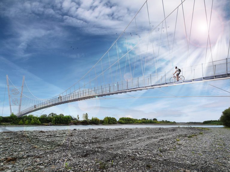
The Waroa Clip-on steel truss walkways are an economic but vibrant cyclebridge solution. The crossing features seven 25m long steel truss bridges to span the Wairoa River attached to the existing road bridge. The concept was the winning solution as part of the successful Brian Perry Civil tender for the overall clip-on works. The vibrant steel warren trusses designed by DC Structures Studio were put forward as an “alternative design” to the original design featuring FRP trusses. The steel truss bridge concept was 50% lighter than the FRP trusses and circa 20% cheaper, which gave Brian Perry a huge commercial advantage over other tenderers. The works were delivered for Western Bay of Plenty District Council and the Waka Kotahi (NZ Transport Agency).
For information relating to Truss Bridge Design Process see more info below.
The steel warren trusses designed by DC Structures Studio combine seamlessly with the architectural pier attachments designed by Beca Ltd. The overall warren truss + pier truss solution is considered a “game changer” for maximising the use of existing bridge assets to help improve walking and cycling in and around the Bay of Plenty region. The cycleway truss bridges are painted in vibrant a “Resene Guru” colour scheme to help create an interesting and playful overall aesthetic that we hope will bring further interest and uptake in use of these important cycling assets.


Wairoa River Truss Bridge Specs
Date of construction = 2019/2020
Truss + Pier cost = Circa $4.2M
Span = 7 x 25m
Width = 2.15m
Barrier height = 1.4m;
Live Load = Pedestrians and Cyclists (4KPa)
Design Code = NZTA Bridge Manual 3rd Edition
Bridge Form = Steel warren truss and fibre composite deck
Paint System = Polyurethane 2-pack paint system (PUR5)
Truss Bridge Design Process
Below are some of the key design methods and assumptions that were important for designing this bridge. The information is related to a warren truss but is equally applicable to a wide array of different truss forms such as Howe and Pratt trusses etc. Leave us a question in the comments if you want to know more.
Truss Bridge Analysis Model (using SAP2000)
The walkway steelwork is modelled and then assessed using a 3D frame element model built using SAP2000 v21 software. The walkway was assumed pinned at one end and allowed to “roll” at the other because of the use of slotted hold-down bolts. See screenshot below.

As per Section 3.2 of CIDECT Guide 1 (Design Guide for Circular Hollow Section (CHS) Joints Under Predominantly Static Loading 2008) the top and bottom chords have been modelled as continuous members and the diagonals and plan bracing have been modelled as pinned members. Because we are relying on the diagonals to perform the role of the “U-frame” for restraining the top chord from lateral buckling, and also as vertical post for barrier forces, the diagonals are only released for moment in the plane of the truss and are assumed fixed out of plane.
Modelling of gap joints in trusses
Gap joint are used in truss bridge designs to prevent overlapping of members that can add to the fabrication costs. Introducing gap joints which prevent overlaps, adds some analysis complexity but is recommended for economy during fabrication.
As per Figure 3.2 of CIDECT Guide 1, the gap joints in the Wairoa Truss Bridge have been modelled by allowing for a 30mm vertical eccentricity either side of the chords members. These eccentricities are modelled as rigid members and ensure effects from eccentricities are included in the member design actions. The eccentricity of 30mm is used to enable a gap joint of circa 20mm rather than an overlap joint and thus reduce fabrication complexity. 30mm meets the CIDECT recommended limit of e ≤ 0.25d = 50mm.

All compression (and tension) diagonals are conservatively assumed to have effective length of KL = L, i.e. taken as the simply supported distance between joint nodes.
The overall analysis has been based on the Span #2 truss. All trusses have the same 24,570mm long truss configuration with joint nodes spaced 1890mm longitudinally and 1545mm vertical (centre of chord to centre of chord) in a warren truss configuration with 13 bays. To accommodate the span length (measured centre of bearing to centre of bearing), “support offsets” have been included as shown in the figure below.

U-frame action and effective length of top chord
The truss bridge design used for the Wairoa River bridge is what is often often referred to an an “open truss” or “walk-through truss”. These types of truss bridge designs are perfect for pedestrian bridges where the top chord can operate as the top of the handrail. To accommodate this open top approach the top chord cannot have any direct lateral bracing to prevent it from buckling. Optimizing these truss bridge types is all about determining the most suitable effective length for buckling of the compression chord.
As discussed in Section 3.3.2 of CIDECT 1 it is not necessary to design unrestrained chords based on the full truss span length. Effective length for these members will be based on the stiffness of the diagonals and the restraint to transverse movement provided by the “U-frame” action created by vertical diagonals in combination with the cross beams.
Walk-through trusses are perfect for pedestrian bridges since the top chord can operate as the top of the handrail. Optimizing these truss bridge types is all about determining the most suitable effective length for buckling of the compression chord. This is achieved by quantifying and utilizing U-frame action.
Dan Crocker – Wairoa River Bridge Design Engineer
To assess the performance of the U-frame action, a buckling analysis of the “dead load + live load” (SLS1A = DLsteel + SDL + FP) combination was performed and the buckling shape of the top chord was visually inspected to derive a credible top chord effective length. It was found that the factor for buckling of the top chord occurred at 14.5 times the SLS1A condition. As shown in Figures 8-3 and 8-4 below it was found that the top chord buckles as an “n=3” (3 wave) buckling member. Effective lengths were conservatively measured as the distance between points where the inflection crosses the zero transverse movement axis. The critical buckling length has thus been assumed as 5 bays = 9450mm centered over the mid-span. It was noted that if the effective length was measured between the points of inflection, a less conservative critical effective length of 7560mm (4 bays) could be used (shown with dashed lines in the figure below).


Once the effective length for the compression chord is determined, all chords and diagonals can be designed and checked for their demands as generated by the SAP2000 model and the various load combinations. Typically the chords and diagonals are designed for pure axial demands in the “Dead + Live” combinations. Lateral load cases such as wind, seismic, etc. may also impose additional bending in the direction of the U-frame (out of plane) that need to be checked.
Truss Connections Design (using FE analysis)
The steel truss connections were modelled using proprietary finite element (FE) connection modelling software Idea Statica v10.0. The software was used to confirm stresses and strains in plate members and to design welds. Refer to screenshot below which shows critical stresses (red) for a (θ=0.9) x 350MPa = 315MPa capacity material. All demands are within capacity and thus deemed acceptable.
Independent verification modelling was also performed in Abaqus CAE software to confirm the outputs of the Idea Statica software. These results were consistent with Idea Statica as can be seen in comparing Figures below. The 5mm mesh was also used to confirm the critical stresses at the weld region. The maximum weld force was measured as 1296N/mm at the diagonal connection to the truss. This critical weld force is less than the effective strength of a Fu=490MPa 8mm fillet weld (with 6mm throat) which has a strength of 1411N/mm (D/C = 92%). All plates and welds were found to be within code limits and the maximum plastic strain of 0.07% is well below the 5% limit of EN1993-1-5[1].


[1] EN1993-1-5, App. C, Par. C.8, Note 1
Truss Bridge Engineering Standards
The following codes / specifications have been used for the design and may be suitable for the majority of truss bridges:
• NZTA 3rd Edition Bridge Manual 2013 including amendments September 2014 [NZTABM];
• AS/NZS 2312.1 2014 Guide to the Corrosion Protection of Steel – Paint Systems;
• NZS1170.0 to .5 Australia and New Zealand Structural Design Actions;
• AS 5100.6 Bridge Design, Part 6-2004 – Steel & Composite Bridge Design;
• AS 5100.4 Bridge Design, Part 4-2004 – Bearings and deck joints;
• NZS 3404 Design of Steel Structures 1997;
• NZS 3101 Design of Concrete Structures 2006;
• BD37/01 Loads for Highway Bridges 2001 (now withdrawn in UK but still referenced in NZTABM);
• CIDECT 1 – Design Guide (1) for Circular Hollow Section (CHS) Joint Under Predominantly Static Loading 2008;
The above can be equally used for the majority of truss bridge engineering in NZ and Australia.
Cycle Bridge Delivery Team
Overall Client = Western Bay of Plenty / Waka Kotahi (NZ Transport Agency)
Client Rep = Beca Ltd
Design and Construct Lead = Brian Perry Civil
Truss Architect = DC Structures Studio
Truss Engineer = DC Structures Studio
Truss + Pier Constructor = Brian Perry Civil
Truss + Pier Fabrication = Hornell Industries (trusses) & Eastbridge (Piers)
Pier Engineer = Beca Ltd