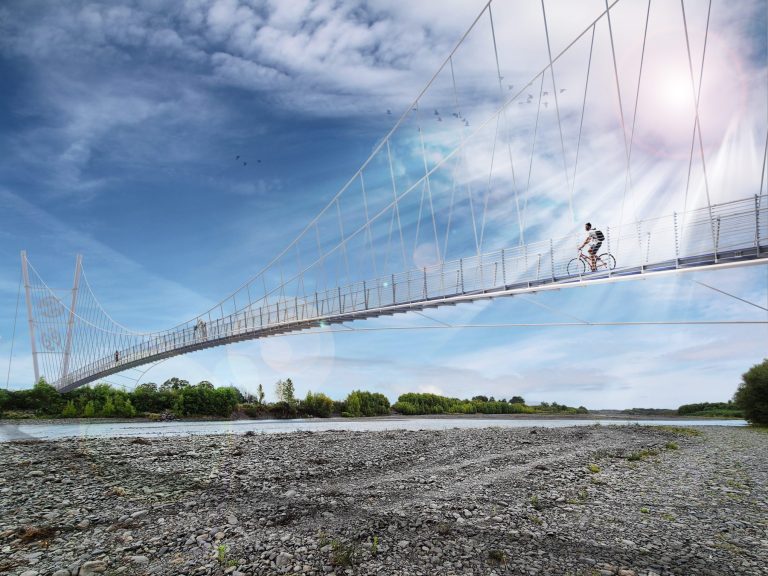
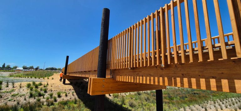
Plummers Point Glulaminated Timber Bridge was a cyclebridge design we did for Edifice Contracts Limited (Edifice) as part of the July 2017 “Omokoroa 3 Bridges” Tender. The project was for the design and construction of three cyclebridges for Western Bay of Plenty.
Our design for the Plummers Point Cycle Bridge is a 3-span cantilever beam glulaminated timber bridge with a span configuration of 9m / 28m / 9m. The piers have been placed outside of the waterway envelope as defined by the existing railway bridge spill though abutments and piers. The design we developed removed the need for any lifting or piling to be done from the water and thus significantly reduced cost and safety/environmental issues inherent with waterway works.
Not only does this innovative structural arrangement enable us to present an economic design but it also has a streamlined an expressive form that has significant architectural merit.
By working closely with the contractor, we were able to present the most competitively priced design and construct package which was $200,000 below the original $1.5M project estimate (estimate for all three bridges) and thus represented great value for the local community. Also see Newnham Road Cycle Suspension Bridge.
Key Glulaminated Timber Bridge Design Criteria
The overall Omokora Cycleway is to be a Grade 2 cycle track (easy) as per NZCTDG. As such it was considered appropriate to design bridges (which are generally less than 100m of the track at any point) for one grade higher and the bridges are therefore designed to Grade 3 requirements as set out by NZCTDG. This improved our ability to design economic bridges and was particularly relevant to bridge grades, turning radii, and barrier design loads:
- Span arrangement = 9m / 27m / 9m;
- Minimum bridge width = 2.4m measured at the deck surface;
- Minimum barrier height = 1.4m;
- Sloped surfaces to have non-slip surfacing;
- Barrier infill to be non-climbable as per NZBC F4;
- Longitudinal joints are not be used;
- Minimum headroom to cycle-path and bridges = 2.4m;
- Maximum allowable pathway gradient = 7.5% (Grade 3);
- Radius of turns: 2.5 m minimum with at least 4 m desirable to outside of turn (Grade 3);
- Design life for all structural elements is 50 years minimum;
- Glulaminated timber bridge beams grade GL10 (Modulus of elasticity = 10,000 MPa, Characteristic bending = 22 MPa).


Glulaminated Timber Bridge Clearance
Plummers Point Bridge and Newnham Road Bridge will have a soffit of all superstructure elements 1500mm minimum above MHWS. This is considered suitable to accommodate flooding, freeboard and climate change during the life of the structure. This elevation is also assumed to put superstructure elements outside of the salt water splash zone.
A zone of 3m wide through the centre of the Plummer Point Bridge and Newnham Road Bridge crossings will be designed to have a minimum clearance of 2.5m above MHWS to accommodate the passage of small watercraft such as kayaks and canoes.
Glulaminated Timber Bridge Design and Construct (D&C) Process
During early collaborative discussions between Edifice and DC Structures Studio (DCSS) it was quickly agreed that piling in the waterway was the most expensive part of the build and a key area for innovation. This design is preferred as it prevents the need for any piling or lifting to be done from the water. The cantilever beams were developed so that the centre of mass was located toward the bank location meaning that lifting equipment could be significantly reduced (compared to long-reach lift required for beam mass centred over the waterway).
Services provided by DC Structures Studio:
- Developed in consultation with contractor efficient bridge types specific to the site (use of a cantilever glulaminated bridge prevented costly piling and lifting from the waterway);
- Sourced and coordinated Geotech, Planning, and Peer Reviewer inputs (preference was to use locally available Planning and Geotech);
- 3D Sketchup models created showing bridge in local topography (done in-house and helps with the Constructor’s ability to understand and plan around existing site constraints);
- Produced CAD General Arrangement (GA) drawings;
- 3D visualisations (a great way to show the client what they are getting!);
- Tender design Statement. This was a discussion document identifying key assumptions, exclusions, design codes, materials, durability, etc.;
- Design stage programme (showing how planning, investigation, Geotech and design would all need to overlap);
- Tender design analysis on key structural elements and provided info and assumptions to Contractor pricing team;
- Developed competitive pricing for the Structural, Geotechnical, Planning and Peer Reviewer detailed design and construction phase fees.


